Understanding No Load Testing of Transformers: Exploring the Basics
No Load Testing is a special kind of test that is done on transformers to see how well they work when there is no load or electrical load attached to them. It involves putting a voltage on the low voltage side of the transformer at the rated frequency without plugging anything into the high voltage side. The transformer’s voltage, current, and amount of power used are then measured from the low-voltage side.
Why is No Load Testing Important?
No load testing is important for more than one reason. First, it can be used to figure out how much power is lost in the transformer’s core. Core losses are caused by hysteresis and eddy currents in the magnetic core of the transformer. Since these losses don’t depend on how much the transformer is being used, they can be used to figure out how efficient the transformer is as a whole.
Second, no load testing can be used to find out how much current the transformer draws when it is not being used. The current that flows through the transformer when it is not being used is called “no-load current.” Even though this current is usually very small, it can still heat up the transformer a lot. Testing with no load can be used to find transformers that have too much current when there is no load, which could cause them to break down early.
No-load Test Circuit Diagram
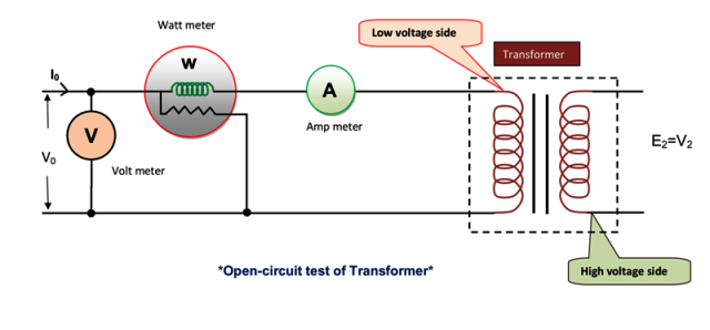
The high voltage winding is left open for the Open circuit test.In the low voltage winding of the transformer, there are wattmeters, voltmeters, and ammeters connected together. The figure shows how to connect the Wattmeter, voltmeter, and ammeter. Now, normal voltage was put on the low voltage winding, and wattmeters, voltmeters, and ammeters that were connected to the low voltage winding were read.
- The Wattmeter measures the iron loss of the transformer, which is made up of the hysteresis loss and the eddy current loss.
- The cu-loss is very small in the low voltage winding and doesn’t happen at all in the high voltage winding when there is no load.
- The Ammeter measures the very small current I0 when there is no load, which is between 2% and 10% of the rated load current.
- The voltmeter measures the normal voltage that is applied to the low voltage winding.
Let W is the wattmeter reading and V1 is the applied voltage and I0 is the ammeter reading ,
Then
W = V1I0Cos Φ0
∴ cosΦ0= W/V1I0
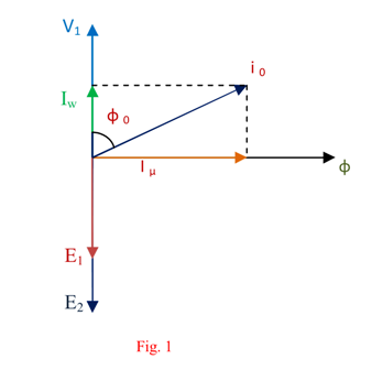
And Iµ = is the magnetizing component of no load current, Iw is the core loss component of no load current, from the vector diagram of no-load transformer,
Iµ = I0 sin Φ0, Iw= I0 cosΦ0,
∴ X0 = V1/ Iµ and R0 = V1 /Iw Thus,
Z0=√(R02+ X02)
The admittance is the inverse of impedance. Therefore,
Y0= 1/Z0
The conductance G0 can be calculated as,
G0=W/V12
Hence the exciting susceptance ,
B0=√(Y02– G02)
Why are copper losses neglected in open circuit test?
For this test, a voltage is put on the low voltage side of the transformer at the rated frequency, but nothing is connected to the high voltage side. As the current without a load is very small (2%–6%), the copper loss without a load is very small compared to the iron loss, so the copper losses (0.04%–0.36%) are not taken into account in an open circuit test.
Why is kept open high voltage side of transformer during measuring the open circuit test?
During the open circuit test, the high voltage side of a transformer is left open because it isn’t necessary to measure the voltage or current on that side. The open circuit test is used to measure a transformer’s core losses, which are the same no matter how much voltage or current is on the high voltage side.
For the open circuit test, one winding of the transformer is hooked up to a power source and the other winding is left open. Measurements are made of the voltage that is applied to the energised winding and the current that flows through the energised winding.
The test isn’t over until the high voltage side is left open because the metering arrangement works better on the low voltage side than on the high voltage side.
Maintenance Of Equipments
Now, let’s talk about the Preventive maintenance of the following equipment.
- Transformer Preventive Maintenance.
- Street Light Preventive Maintenance.
- AC Maintenance.
- DG Set Maintenance.
- Preventive Maintenance of ACB.
- Preventive Maintenance of Capacitor Bank.
- Preventive Maintenance of Lifts.
- Preventive Maintenance of Earthing.
- Preventive Maintenance of Ceiling Fans.
- Preventive Maintenance of Power Panels.
- Preventive Maintenance of Circuit Breakers.